- Huyett Marketing Department
- 08/12/2020
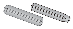
Grooved pins are solid press fit fasteners that are quickly gaining in popularity. They feature three parallel grooves and are commonly used as locking devices, pivots, levers, or locating elements.
Design Considerations
A GROOVED PIN IS NOT GROOVED, IT IS FLUTED.
This is the most important concept to understand about grooved pins.
During manufacturing, the grooves are formed by a swaging operation;
material is displaced, but not removed.
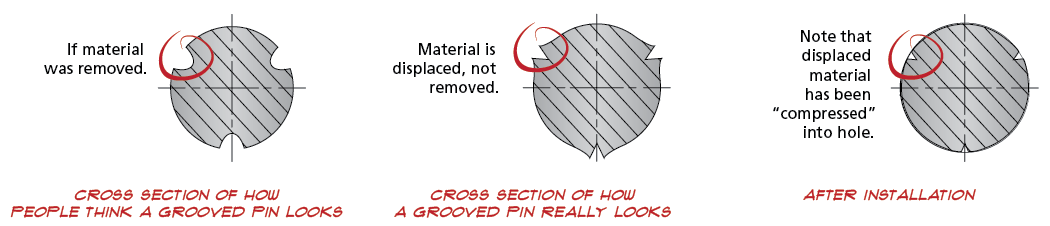
Grooved pins' holding power comes from the radial forces generated when the swaged material is compressed in the hole.
PARALLEL GROOVES DETERMINE WHERE AND HOW MUCH THE PIN WILL HOLD.
Quarter-Length
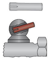
Non-fluted portion can be used as a lever
Half-Length
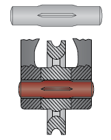
Centered as shown, the ends can be used as roller shafts
Full-Length
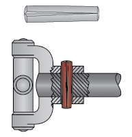
Holds entire length of pin
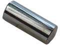
Pilots
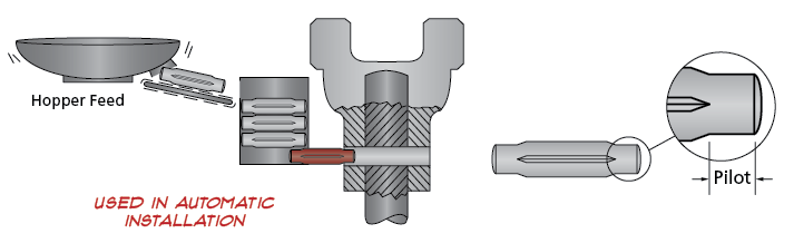
Pilots are the small non‑fluted portions at the ends of the pin and should not be confused with longer non‑fluted portions of the pin. They appear smaller in diameter than the grooved portion. Pilots simplify installation by creating a starting position.
Annular Grooves
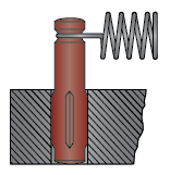
Used to hold a compression spring in position
Grooved Pin Types
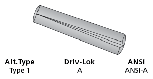
Type A / DIN 1471
Features three full‑length tapered grooves. Popular in applications requiring a strong locking effect and ease of assembly. Used in place of taper pins, rivets, set screws, and machine keys.
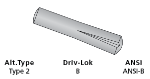
Type B / DIN 1472
Features three half‑length tapered grooves. Commonly used as a hinge or pivot pin. The grooved end is the locking portion, while the other end serves as a handle. Also works in dowel applications.
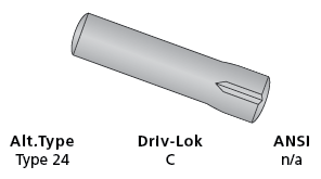
Type C
Features three quarter‑length parallel grooves. Widely used in hinge applications. The long lead eases insertion.
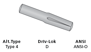
Type D / DIN 1474
Features three half‑length reverse tapered grooves. Provides maximum holding power. Permits easy insertion into blind holes.
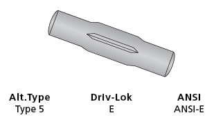
Type E / DIN 1475
Features three quarter‑length parallel grooves located equidistant from each end. Commonly used as a T‑handle on valves and tools.
Type G / DIN 1469
Features three half‑length parallel grooves with a pilot on the opposite end. Permits versatile use in blind or through holes as a spring anchor pin.

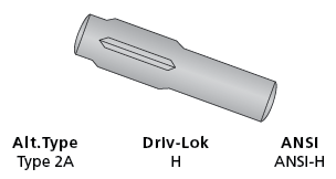
Type H
Features three half‑length parallel grooves, but do not have a pilot. When pressed in place, the grooved portion locks in one part while the other end is free to serve as a locater or hinge.
Type U
Features three full‑length parallel grooves with a pilot on both ends. Ideal for hopper or automatic feeding.

DIN 1470 & 1473
Features three full‑length parallel grooves. DIN 1470 pins have a short pilot and DIN 1473 pins have a chamfer. Recommended for applications that require maximum locking effect, where severe vibration and/or shock loading are present.
Grooved Pins
Common Names:
Grooved Pins, Driv‑Lok Pin
Applicable Standards:
ASME B18.8.2, DIN specifications: 1469, 1470, 1471, 1472, 1473, 1474, and 1475
Fabrication:
Parts are turned and grooves are swaged, a process that disrupts the surface of the pin, without removing material. The swaged areas are compressed into the hole, creating tension and force for holding the part in place.
How to Identify:
Nominal diameter x nominal length; define form. The form is determined by the location of the grooves and the presence of pilots and other features.
Common Uses:
Mostly original equipment. Used in place of a dowel or rolled pin (Type A); or as a handle (Type E); a pivot point (Type C), or spring anchor (Type G).
Comments:
Numerous designs. While metric and imperial pins have similar features, they are manufactured to different specifications.
